1. Make http-video layer7-protocol
/ip firewall layer7-protocol add name=http-video
regexp=http/(0\.9|1\.0|1\.1)[\x09-\x0d ][1-5][0-9][0-9][\x09-\x0d -~]*(content-type: video)
2. Make Mangle Mark Packet http-video
/ip firewall mangle
add action=mark-packet chain=forward
comment="http-video mark-packet" disabled=no
layer7-protocol=http-video new-packet-mark=http-video passthrough=no
3. Make Queue Simple http-video
/queue simple
add max-limit=0/64000 name=http-video packet-marks=http-video
Read More...
Tuesday, September 22, 2009
Limit Youtube Video Streaming from mikrotik
Monday, September 14, 2009
Install Webmin di Ubuntu Server
Webmin adalah aplikasi bantu untuk memudahkan manajemen server kita. Selain web-base webmin juga mudah dimengerti bagi yang masih baru (seperti saya) dalam dunia ubuntu. Bagi yang menggunakan ubuntu server, silahkan ikuti petujuk dibawah ini, :
Untuk menginstall Webmin yang diperlukan adalah :
* ubuntu server yang terhubung dengan internet
Setelah syarat diatas terpenuhi anda lakukan 6 langkah dibawah ini :
1. ketikan perintah "sudo vi /etc/apt/sources.list"
2. setelah terbuka isikan baris berikut ini pada baris yang paling bawah :
"deb http://download.webmin.com/download/repository sarge contrib" (tanpa tanda kutip)
3. Setelah itu tutup dan simpan dengan mengetikkan ":wq" (tanpa tanda kutip)
4. Lakukan update source dengan mengetikkan "apt-get update" (tanpa tanda kutip), Tunggu sampai selesai
5. lalu instal webmin dengan mengetikkan "sudo apt-get install webmin" tekan Y/yes jika ada pertanyaan
6. Tunggu dan nikmati aplikasi bantu server anda
Menggunakan webmin mudah dan sangat "user friedly". ohya karena webmin menggunakan port 10000 maka jika anda mengetikkan di browser tambahi dengan https://ip-ubuntu-server:10000. Demikian semoga Webmin bisa membantu dalam memudahkan memanage server anda. Read More...
Saturday, September 12, 2009
Mendalami HTB pada QoS RouterOS Mikrotik
Implementasi QoS (Quality of Services) di Mikrotik banyak bergantung pada sistem HTB (Hierarchical Token Bucket). HTB memungkinkan kita membuat queue menjadi lebih terstruktur, dengan melakukan pengelompokan-pengelompokan bertingkat. Yang banyak tidak disadari adalah, jika kita tidak mengimplementasikan HTB pada Queue (baik Simple Queue maupun Queue Tree), ternyata ada beberapa parameter yang tidak bekerja seperti yang kita inginkan.Beberapa parameter yang tidak bekerja adalah priority, dan dual limitation (CIR / MIR).
Pada pembahasan artikel ini, kita akan mengambil contoh sebuah sistem QoS sederhana, di mana kita ingin mengalokasikan bandwidth sebesar 400kbps untuk 3 client, di mana masing-masing client bisa mendapatkan maksimal 200kbps. Di antara ketiga client tersebut, memiliki prioritas yang berbeda, yaitu: 1,2, dan 3.
Untuk mempermudah pemantauan dan pembuktian, kita akan menggunakan queue tree.
Cara paling mudah untuk melakukan queue dengan queue tree, adalah dengan menentukan parameter :
parent (yang harus diisi dengan outgoing-interface),
packet-mark (harus dibuat terlebih dahulu di ip-firewall-mangle),
max-limit (yang merupakan batas kecepatan maksimum), atau dikenal juga dengan MIR (Maximum Information Rate)
Untuk percobaan awal, semua priority diisi angka yang sama: 8, dan parameter limit-at tidak kita isi. Gambar berikut ini adalah ilustrasi apa yang akan terjadi dengan konfigurasi di atas.
Karena alokasi bandwidth yang tersedia hanya 400kbps, sedangkan total akumulasi ketiga client melebihinya (600 kbps), maka ketiga client akan saling berebut, dan tidak bisa diprediksikan siapa yang akan menang (menggunakan bandwidth secara penuh) dan siapa yang akan kalah (tidak mendapatkan bandwidth yang sesuai).
Misalkan q1 adalah client dengan prioritas tertinggi, dan q3 adalah client dengan prioritas terbawah. Kita akan mencoba memasukkan nilai prioritas untuk masing-masing client sesuai dengan prioritasnya.
Tampak pada gambar di atas, meskipun sekarang q1 sudah memiliki prioritas tertinggi, namun ketiga client masih berebutan bandwidth dan tidak terkontrol.
Gambar berikut akan mencoba mengimplementasikan nilai limit-at. Seharusnya, limit-at adalah CIR (Committed Information Rate), merupakan parameter di mana suatu client akan mendapatkan bandwidthnya, apapun kondisi lainnya, selama bandwidthnya memang tersedia.
Ternyata q1 masih tidak mendapatkan bandwidth sesuai dengan limit-at (CIR) nya. Padahal, karena bandwidth yang tersedia adalah 400kbps, seharusnya mencukupi untuk mensuplai masing-masing client sesuai dengan limit-at nya.
Berikutnya, kita akan menggunakan parent queue, dan menempatkan ketiga queue client tadi sebagai child queue dari parent queue yang akan kita buat. Pada parent queue, kita cukup memasukkan outgoing-interface pada parameter parent, dan untuk ketiga child, kita mengubah parameter parent menjadi nama parent queue. Pertama-tama, kita belum akan memasukkan nilai max-limit pada parent-queue, dan menghapus semua parameter limit-at pada semua client.
Tampak pada contoh di atas, karena kita tidak memasukkan nilai max-limit pada parent, maka priority pada child pun belum bisa terjaga.
Setelah kita memasang parameter max-limit pada parent queue, barulah prioritas pada client akan berjalan.
Tampak pada contoh di atas, q1 dan q2 mendapatkan bandwidth hampir sebesar max-limitnya, sedangkan q3 hampir tidak kebagian bandwidth. Prioritas telah berjalan dengan baik. Namun, pada kondisi sebenarnya, tentu kita tidak ingin ada client yang sama sekali tidak mendapatkan bandwidth.
Untuk itu, kita perlu memasang nilai limit-at pada masing-masing client. Nilai limit-at ini adalah kecepatan minimal yang akan di dapatkan oleh client, dan tidak akan terganggu oleh client lainnya, seberapa besarpun client lainnya 'menyedot' bandwidth, ataupun berapapun prioritasnya. Kita memasang nilai 75kbps sebagai limit-at di semua client.
Tampak bahwa q3, yang memiliki prioritas paling bawah, mendapatkan bandwidth sebesar limit-at nya. q1 yang memiliki prioritas tertinggi, bisa mendapatkan bandwidth sebesar max-limitnya, sedangkan q2 yang prioritasnya di antara q1 dan q3, bisa mendapatkan bandwidth di atas limit-at, tapi tidak mencapai max-limit. Pada contoh di atas, semua client akan terjamin mendapatkan bandwidth sebesar limit-at, dan jika ada sisa, akan dibagikan hingga jumlah totalnya mencapai max-limit parent, sesuai dengan prioritas masing-masing client.
Jumlah akumulatif dari limit-at tidaklah boleh melebihi max-limit parent. Jika hal itu terjadi, seperti contoh di bawah ini, jumlah limit-at ketiga client adalah 600kbps, sedangkan nilai max-limit parent hanyalah 400kbps, maka max-limit parent akan bocor. Contoh di bawah ini mengasumsikan bahwa kapasitas keseluruhan memang bisa mencapai nilai total limit-at. Namun, apabila bandwidth yang tersedia tidak mencapai total limit-at, maka client akan kembali berebutan dan sistem prioritas menjadi tidak bekerja.
Sedangkan, mengenai max-limit, max-limit sebuah client tidak boleh melebihi max-limit parent. Jika hal ini terjadi, maka client tidak akan pernah mencapai max-limit, dan hanya akan mendapatkan kecepatan maksimum sebesar max-limit parent (lebih kecil dari max-limit client).
Jika semua client memiliki prioritas yang sama, maka client akan berbagi bandwidth sisa. Tampak pada contoh di bawah ini, semua client mendapatkan bandwidth yang sama, sekitar 130kbps (total 400kbps dibagi 3).
Yang perlu diingat mengenai HTB:
HTB hanya bisa berjalan, apabila rule queue client berada di bawah setidaknya 1 level parent, setiap queue client memiliki parameter limit-at dan max-limit, dan parent queue harus memiliki besaran max-limit.
Jumlah seluruh limit-at client tidak boleh melebihi max-limit parent.
Max-limit setiap client harus lebih kecil atau sama dengan max-limit parent.
Untuk parent dengan level tertinggi, hanya membutuhkan max-limit (tidak membutuhkan parameter limit-at).
Untuk semua parent, maupun sub parent, parameter priority tidak diperhitungkan. Priority hanya diperhitungkan pada child queue.
Perhitungan priority baru akan dilakukan setelah semua limit-at (baik pada child queue maupun sub parent) telah terpenuhi.
Panduan praktis cara perhitungan limit-at dan max-limit
Di asumsikan bandwidth yang tersedia sebesar 1000kbps. Dan jumlah seluruh client adalah 70. Yang perlu diketahui adalah :
Berapa jumlah maksimal client yang menggunakan internet pada saat yang bersamaan. Jumlah ini belum tentu sama dengan jumlah komputer yang ada, apabila semua client tidak pernah terkoneksi secara bersamaan. Sebagai contoh, untuk kasus ini kita asumsikan adalah 50.
Berapa jumlah minimal client yang menggunakan internet pada saat yang bersamaan. Sebagai contoh, untuk kasus ini kita asumsikan adalah 10
Maka, untuk setiap client (1 client dibuatkan 1 rule queue), limit-at nya adalah 1000 / 50 = 20kbps, dan max-limit nya adalah 1000 / 10 = 100 kbps.
Jangan lupa untuk menambahkan parent dengan max-limit sebesar 1000kbps (tidak perlu limit-at), dan memasukkan semua queue client di bawah parent queue. Jika untuk terminal tertentu membutuhkan priority lebih besar, maka kita bisa menggunakan priority yang berbeda-beda, tergantung dengan urutan prioritasnya.
source : www.mikrotik.co.id
Read More...
Squid zph (Zero Penalty Hit) and Mikrotik
Bonus tambahan dari squid 2.7-stable3 adalah fungsi zph yang sudah terintegrasi.
ZPH sendiri adalah Zero Penalty Hit, penjelasan-nya bisa dibaca di http://zph.bratcheda.org/
Pada 2.7 sudah masuk dalam core engine squid .
.
Sebelum versi 2.7 harus melakukan patch.
Dengan mengedit sekian baris di squid dan penambahan 2 rule di mikrotik, akhirnya paket TCP_HIT pun dapat di baypass. Semua request dari klient mendapat traffic full sebesar local-loop yang dipunyai.
#tcp_outgoing_tos 0x30 localnet
zph_mode tos
zph_local 0x30
zph_parent 0
zph_option 136
Di mikrotik di bagian firewall mangle ditambahkan.
Untuk Mikrotik v.2.xx
/ ip firewall mangle
add chain=prerouting action=mark-packet new-packet-mark=proxy-hit
passthrough=no tos=48 comment="squid" disabled=no


Untuk Mikrotik v.3.xx
add chain=prerouting action=mark-packet new-packet-mark=proxy-hit
passthrough=no dscp=12 comment="squid" disabled=no

Di bagian Queue, pada baris paling atas.
/ queue simple
add name="Proxy" dst-address=0.0.0.0/0 interface=all parent=none packet-marks=proxy-hit
direction=both priority=1 queue=default-small/default-small limit-at=0/0 max-limit=0/0
total-queue=default-small disabled=no
Gambar topologi yang saya pakai seperti dibawah ini.

Paket marking zph juga masih bisa dikenali di router hotspot.
Jadi pelanggan hotspot akan merasakan loading konten yang cepat bila konten tersebut sudah ada dicache squid.
Tampilan grafik zph in action

http://human.network.web.id/2008/07/03/squid-zph-and-mikrotik/
http://mum.mikrotik.com/presentations/EG07/sunday.pdf
Read More...
Saturday, August 15, 2009
802.11b WLAN Waveguide Antennas Unidirectional & Omnidirectional High gain, Simple construction
Waveguides? Aren't they a bit complicated?
In a word, Yes! Microwave technology is pretty esoteric, and it used to be reserved for the "spooks" designing electronic warfare systems, radars, and the like.
But microwave equipment has been steadily penetrating into mainstream applications. Microwave ovens (operating at 2.4GHz) have already been with us for several decades. These have been joined by satellite dishes and LNBs operating at 10GHz and more recently, multichannel 2.4GHz cordless phones.
Microwave technology seems complex because we have left the boffins in charge for too long. Microwave text books have been written by academics who revel in every detailed equation. But you don't really need to know about Poynting vectors or Maxwell's equations to deploy a really effective Wireless LAN. Let me show you how simple it really is...
What is the 2.4GHz ISM Band?
Wireless networking systems using the 802.11b standard operate in the 2.4GHz ISM band. Other services, including microwave ovens, medical equipment, and cordless phones also operate in the ISM band. The IEEE 802.11b standard defines how WLAN networking will be configured, and how interference can be minimized from the other services operating at the same frequencies.
| Channel ID | US/Canada | Europe | France | Spain | Japan |
| 1 | 2412 | 2412 | - | - | 2412 |
| 2 | 2417 | 2417 | - | - | 2417 |
| 3 | 2422 | 2422 | - | - | 2422 |
| 4 | 2427 | 2427 | - | - | 2427 |
| 5 | 2432 | 2432 | - | - | 2432 |
| 6 | 2437 | 2437 | - | - | 2437 |
| 7 | 2442 | 2442 | - | - | 2442 |
| 8 | 2447 | 2447 | - | - | 2447 |
| 9 | 2452 | 2452 | - | - | 2452 |
| 10 | 2457 | 2457 | 2457 | 2457 | 2457 |
| 11 | 2462 | 2462 | 2462 | 2462 | 2462 |
| 12 | - | 2467 | 2467 | - | 2467 |
| 13 | - | 2472 | 2472 | - | 2472 |
| 14 | - | - | - | - | 2484 |
A WLAN receiver can use any of these channels, and can automatically hop from channel to channel if interference is encountered. An 802.11b antenna for the US and Canada should radiate well between 2410 and 2460 MHz.
| Slotted Waveguide Antennas Unlike wideband antennas like the biquad, slotted waveguides are resonant antennas, and have a relatively narrow operating frequency range. The designs I am describing on this page have an adequate bandwidth for any WLAN, but they have been carefully designed and must be equally carefully constructed. The major attraction of a slotted waveguide design is its simplicity. Once you have built the first one it is very simple to build many more. The gain varies little across the 802.11b spectrum, dropping a little bit at the extreme ends. |
How I Produced These Designs and Charts
These slotted waveguide designs are the result of lengthy simulation using Zeland Software's Fidelity and IE3D electromagnetic simulators. Fidelity is much better at modelling waveguide structures than my favorite simulator, NEC2, but it is quite an expensive package, with a long learning curve...
Simulation can give you much more information about the performance of a microwave antenna than you get from building it. This is because there are severe limitations in the accuracy of measurements at microwave frequencies. Simulation makes it easier to see subtle interdependencies that would be very difficult to measure. In this case, I used the simulation to tell me how the antennas should behave, and then verified the performance both in my lab and on my antenna 'test range'. The results were surprisingly accurate - and attest to the quality of the Zeland Fidelity software.
 | How a Waveguide Antenna Works A waveguide is a very low loss transmission line. It allows us to propagate signals to a number of smaller antennas (slots). The signal is coupled into the waveguide with a simple coaxial probe, and as it travels along the guide it traverses the slots. Each of these slots allows a little of the energy to radiate. The slots are in a linear array pattern, and the total of all the radiated signals adds up to a very significant power gain over a small range of angles close to the horizon. In other words, the waveguide antenna transmits almost all of its energy at the horizon, usually exactly where we want it to go. Its exceptional directivity in the elevation plane gives it quite high power gain. Additionally, unlike vertical colinear antennas, the slotted waveguide transmits its energy using HORIZONTAL polarization, the best type for distance transmission. At left we can see a graphical representation of the E field intensity shortly after starting excitation of an 8 slot waveguide. The slots are to the left of the image. The coaxial probe is at the lower end of the image, and the field can be seen to be clumped at maxima every half wavelength as they travel up the waveguide. The waveguide airspace takes up the middle 1/2 of the bluespace, the rest is air infront of (to the left) and behind (to the right) the antenna. If you click here you can bring up a Windows Media Format Movie version. An MPEG-1 version is at this link. You can see the wave travelling up the waveguide from the probe. The intensity of the E field is given by the color. Here we have primarily blue colors, about -40dB on the final (red) intensity which is achieved once the resonance is fully excited. When the signal first gets to the top and starts reflecting back down the air column it is still green, about -30dB from its ultimate intensity. Reflections are also occuring from the plug at the bottom of the airspace, and the sum effect of all these, including continual drive from the coaxial probe, allows the intensity to build up through yellow and red (0db) signal levels. You can see the signal radiating out the slots at the left of the image. The radiation intensity is less at the top than at the bottom in an 8 slot design, it is hard to radiate perfectly with such a limited number of slots. |
Unidirectional Waveguide Antennas I am going to describe two unidirectional designs. The first has 8 slots and is about 30 inches long. The second has 16 slots and is about 5 feet long. Simple to construct, the 8-slot has been provided as a good starting point for an antenna novice. I built my 8 slot prototype using only hand tools.
| |||||||
Performance 16 slot Unidirectional | ||
 | ||
 High
High 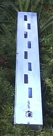
The 16 slot design has been made to radiate over a wider beamwidth by the addition of "wings" to each side of the guide, flush with the front (slotted) surface. It is, of necessity, higher Q, and the higher gain is obtained over a narrower bandwidth. They can be expanded aluminium or sheet, and should extend 9.6 inches beyond the sides of the guide. They act as a ground plane for the slots. Do not change this dimension, it is two electrical wavelengths.
Omnidirectional Slotted Waveguide Antennas
The slotted waveguide has achieved most of its success when used in an omnidirectional role. It is the simplest way to get a real 15dBi gain over 360 degrees of beamwidth.
Horizontal Polarization in a wide area network can often double the number of users that can interconnect without interference. When using horizontally polarized BiQuads, or Patch antennas (provided that they have been tested for good cross-polarization performance) at the client site, these omnis will be 20 dB stronger than the signal from a similar vertical collinear. Conversely, vertically polarized receiver antennas will prefer the vertically polarized colinear over the slotted waveguide by a similar amount. Transmission on an immediately adjacent channel, (say, channels 5 or 7), normally not permissible because of interference, is now possible. So a judicious intermingling of horizontally polarized clients can talk with a horizontal central station on the same or adjacent channels that other clients are using with vertical polarization.To make the unidrectional antenna radiate over the entire 360 degrees of azimuth, a second set of slots are cut in the back face of the waveguide. When looking stright at the face of the waveguide you will be able to see straight through both slots.
Unfortunately, unless a lot of slots are used, the antenna becomes more like a bidirectional radiator, rather than an omnidirectional. This antenna was invented in the 40's, and as our simulation and measurement technologies have become more accurate it is apparent that the slotted waveguide designs we have used in the past are far from optimum. The most common defect is a 'tilt' in the radiation pattern at the extreme ends of the frequency range. This occurs when the wavelength of the signal travelling down the guide differs from the slot spacing.
My current favorite uses 32 slots to get 15dBi of gain, radiated in a uniformly omnidirectional manner. The large number of slots makes it easier to dissipate the energy from the waveguide. Like with the 16 slot unidirectional, two sets of "wings (one set at each slot surface) are required to get equal radiation of energy over a full 360 degrees. Note that a higher Q is necessary to get all the slots illuminated evenly.
 |
Note that the gain vs frequency curve is peaked at 2440, and it radiates well over all 14 channels.
Highly Directional Slotted Waveguide Antennas Sometimes it is useful to have a highly directional antenna. For example, when installing a point-to-point link between two buildings it is not desirable to have a wide angle of coverage. Any interference from other 802.11b devices (or microwave ovens) that are in the radiation zone will affect your link integrity. The ideal antenna for such a situation is a dish, such such as the Primestar dish. When using my Biquad feed, it is possible to reject interference outside the dish's primary 5 degree cone by 30 dB or more.
But, if a 16 slot waveguide antenna is turned to a horizontal position, parallel with the ground, it will radiate vertical polarization. Its directivity in this plane is extremely good. As you can see from the diagram to the left, most of the spurious lobes are more than 20 dB down from the main signal, and they are very narrow (click to enlarge the image). This performance is comparable with my commercial HP2419G Parabolic Grid Antenna... So, if you don't have a dish handy, consider the possibility of using a pair of these slotted waveguides, parallel to the ground. They will work well. Very well... |

Constructional Details for the 8 Slot Unidirectional Antenna
The base extrusion for all my slotted waveguides is 4 inch by 2 inch O.D. rectangular aluminum tubing with approx 1/8 inch thick walls. Inside dimensions are 3.756x1.756 inches (95.4mm x 44.6mm). These inside dimensions are critical, and must be within +- 0.040 inches or +-1mm if the antenna center frequency is to be +- 1 channel. I cut the end inserts from a 5/16 inch by 1 3/4 inch flat aluminum bar extrusion. There - those are the last dimensions I will give in inches, as millimetres are a much more accurate way to describe the dimensions for a microwave antenna. Waveguide antennas are fairly critical in their constructional dimensions, and are easiest to make with a CNC milling machine. I have computed these designs so that they would be easy to replicate, and if you are plus or minus 1 mm the design will work fine - but you must be careful. I used a jig, a hand operated DeWalt heavy duty cut-out tool, a 1/4 inch router bit, and lots of water to 'machine' my slots, and it worked fine (even if it was a little tedious).
"Please machine this slot to 59.417mm in length"
In the days before computing power was free, engineers spent their whole careers deriving formulae to try and describe the operation and design of Slotted Waveguides. You can find designs specified to 1 or 2 decimal places of a millimeter, but I have rounded everything off to the nearest millimeter. Since it was relatively easy for me to "build" structure after structure in the electromagnetic simulator, an understanding of the inter-dependance of each parameter came quite quickly. That understanding takes away the 'black magic' that used to be associated with design of these antenna systems.
Really folks - plus or minus 1 mm will not kill your antenna!
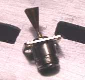
| Coupling the Signal Into the Waveguide As I said above, we are propagating the WLAN signal down a waveguide and then using it to excite a number of elemental radiators, or slots. The first task is to get the signal into the waveguide with a feed probe. Obtain a suitable N connector, for example, the one from Amphenol in Figure 2 of this catalog page. Take a piece of 20mmx40mm copper or brass shim, cut the red portion and form it into the shape of a cone. Solder it to the inner conductor of your Type N connector (see photo). Its length should be 20mm, its largest diameter about 15mm. When soldered to the N connector it should protrude exactly into the center of the waveguide and no further.
Both ends of the waveguide need to be terminated for RF, and the easiest way I found to do this was to cut 3.75 inch pieces (darn - there are those inches again - I will be excommunicated from the microwave community at this rate...) of 5/16 by 1.75 aluminum bar stock. I do not recommend that you make the end plugs sloppily, but good electrical contact is not required. Remember not to have any screws protruding into the waveguide for more than 1/8 inch, especially the screws holding down the N connector. They will affect performance. The total length of air inside the 8+8 slot omnidirectional waveguide, from end to end, is 765mm. Mount the N connector in the center of the widest side, 27.5mm from one end (the 'base') of the airspace in the waveguide and offset 10 mm from the centre line of the face, in the direction as the offset of the first slot.. The wavelength of the radiation passing down the waveguide is longer than a wavelength in free air (it is 161mm in this design). | |
The first slot is centered 1.0 wavelength from the base, at a maximum of the H field in the waveguide. This length is 161mm from the base of the airspace. It is the H component of the field that induces the energy into the slots, and makes them radiate. Each slot is 59mm long, and extends outwards from the centerline for a width of 17mm. The waveguide excites each edge of the slot depending on its position across the wide surface of the guide. If it straddled the exact centre, each edge of the slot would be excited in anti-phase, and there would be no radiation. So we offset the edges of the slots, the more the offset the greater is the energy that is dissipated into each slot. The electrical length of each slot should be 59mm. Do not allow too much kerf at the ends (2 mm radius max). I recommend finishing the cut with a 1/8 inch router bit (or a file). Or you might use the 1/8 bit in a CNC machine to cut the entire rectangular outline. Remember, even though these slots are arranged vertically they radiate horizontal polarization.
For the 8+8 omnidirectional, slots 2 thru 8 are centered at distances of 241, 322, 403, 483, 564, 644 and 724mm from the base of the airspace, staggerred across the centerline. It doesn't matter which direction the first one is cut, but they must alternate. The end plate should create a 765 mm airspace. Looking straight on at the front of the guide you can see right through both the front and back slots.
For the 8 slot Unidirectional:The total length of air inside the 8 slot unidirectional, from end to end, is 760mm. Mount the N connector in the center of the widest side, 25mm from the base of the airspace in the waveguide. The wavelength of the radiation passing down the waveguide is 160mm in this design. The first slot is centered 1.0 wavelength from the base, at a maximum of the H field in the waveguide. This length is 160mm from the base of the airspace. Each slot is 58mm long, and extends outwards from the centerline for a width of 20mm. The waveguide excites each edge of the slot depending on its position across the wide surface of the guide. If it straddled the exact centre, each edge of the slot would be excited in anti-phase, and there would be no radiation. So we offset the edges of the slots, the more the offset the greater is the energy that is dissipated into each slot. The electrical length of each slot should be 59mm. Do not allow too much kerf at the ends. Remember, even though these slots are arranged vertically they radiate horizontal polarization.
Slots 2 thru 8 are centered at distances of 240, 320, 400, 480, 560, 640 and 720mm from the base of the airspace, staggerred across the centerline. It doesn't matter which direction the first one is cut, but they must alternate. The end plate should be to create a 760mm airspace.
 | Constructional Details for 16 and 16+16 Slot Design The correct wavelength for these designs is 161mm. The gain for the 16 slot Unidirectional is 15dBi-17dBi, verified on my test range, across the whole band. On the range the 16 slotter gives slightly higher gain than my Hyperlink Technologies model 2419G Mesh Parabolic, which is "rated" at 19.1dBi gain. The slot width for the 16 slotter is 15mm, for the 32 slotter is 12mm, otherwise the key dimensions are the same.Both PDF and DXF versions of the drawings are available for download. Designs for different size tubing: The optimum design for a 16 slot unidirectional with Indian standard 95.24mm x 38.39mm x 3.18mm tubing gives a wavelength of 163mm. This means that the slots are centered at 163mm / 2 = 81.5mm intervals, rather than the 161mm basis which was used in the Autocad drawings. The N connector for the feed is spaced only 25mm from the base of the airspace, and offset 10mm to the left of the centerline of the guide's face. The length of the aircolumn will be 163 x 8.75 = 1426mm. The slot width for the 16 slotter stays the same at 15mm, and the slot length should be 58mm. For the 16+16 slot omni version use a slot width of 12mm. The feed cone must not protrude more than halfway into the waveguide. With this tubing, the feed cone should not protrude more than 19mm into the tubing. Just use the same drawing as I have shown above, but make it from 17mm X 34mm shim rather than 20x40. 100mm x 50mm x 3mm Metric size tubing: use the same 161mm wavelength and dimensions as for the US designs, but offset the feed point 15mm from center line instead of 10mm to bring the resultant SWR closer to unity.
|
Weather and your Antenna
Use nylon, aluminum or stainless steel screws and fasteners, as suits your preference, not normal (corrosive) ones. Unless you use some low RF loss tape (like mylar or kapton) to cover the slots, bugs will make their homes in the structure and spin their webs across the slots. There are two approaches to this. Either you dont bother about it, and just hose the antenna clean every year or so, or you use, and regularly replace, the protective tape. One tip - there is relatively little RF energy reaching the end away from the base, and if you mount the antenna upside down you can actually cut holes in the end cap so as to let out water and bugs that might otherwise accumulate there. I have simulated that 4 one half inch diameter holes in each vertex of the far end plug do not affect performance in any measurable way. I also simulated the use of a 2.75 by 1.75 inch plug at the far end (with 1/2 inch gaps for cleaning) and found no noticeable degradation. I don't recommend that you encourage bugs to accumulate near the feed probe, however...
So happy WLANing, and please don't forget to email me with your experiences.
Source : http://trevormarshall.com/waveguides.htm
Friday, August 14, 2009
How To Hack Isp To Use Internet For Free (tools and video tutorial)
Superscan
Superscan is a free connect-based port scanning software designed to detect open TCP and UDP ports on a target computer, determine which services are running on those ports, and run queries such as whois, ping, ICMP traceroute, and Hostname lookups.
Superscan 4, which is a completely-rewritten update to the other Superscan, features windows enumeration, which can list a variety of important information dealing with Microsoft Windows such as:
* NetBIOS information
* user and Group Accounts
* Network shares
* Trusted Domains
* Services - which are either running or stopped
Superscan is a tool used by both system administrators, crackers and script kiddies to evaluate a computer's security. System administrators can use it to test for possible unauthorized open ports on their computer networks, whereas crackers use it to scan for a potentially insecure port in order to gain illegal access to a system.
Superscan 4 is produced by the Foundstone, a division of McAfee.
Here are some of the new features in this version.
* Superior scanning speed
* Support for unlimited IP ranges
* Improved host detection using multiple ICMP methods
* TCP SYN scanning
* UDP scanning (two methods)
* IP address import supporting ranges and CIDR formats
* Simple HTML report generation
* Source port scanning
* Fast hostname resolving
* Extensive banner grabbing
* Massive built-in port list description database
* IP and port scan order randomization
* A selection of useful tools (ping, traceroute, Whois etc)
* Extensive Windows host enumeration capability

a-Change Mac Address 5.0
Change Mac Address in seconds! Scan Mac Address within any range of IP address. Exports the scanning results from a Mac Address Lookup list. Spoofing the Mac Address of your network card to any new Mac Address.
Wake on Lan. Win Ipconfig.Port Scan.
Scan any range of IP for the proper Mac Address.
Support changing Mac Address of any network cards under Windows NT/2000/XP/95/98/2003.
Support exporting scanning mac address results to txt file.
A-MAC Address Change is a lightweight, easy-use MAC Address scanning and changing software. Don't let its small size fool you! It's filled with features such as:
* It's shockingly easy to use — just a simple input and click, that's it!
* It can scan any range of IP for the proper MAC Address.
* It supports exporting results of your scan to a text file.
* It runs on all Windows™ operating systems.
* It supports any network cards under Windows Me/95/98/NT/2000/XP/2003/Vista.
* It supports changing back to its original physical address.
* It recommends the proper Ethernet network card.
* It displays the information of your computer.
* It automatically checks the legality of IP range.
* It supports changing MAC searching speed.
But what does all this mean to you? Simple...
* You don't blow your time calling the ISP vendor and ask them to update the registered MAC Address to match the new hardware. Some Cable Modem ISP's assign IP addresses base on the PC's MAC addresses. For whatever reason, if you need to swap 2 PC's regularly to connect to the cable modem, it would be a lot easier to spoof MAC Addresses rather than to change Network Interface Card (NIC).
* You can scan the MAC Address of destination computer.
* You can perform security checking on MAC Address based authentication and authorization systems
* You can build Stand-by (offline) systems with the EXACT same Computer Name, IP address, & MAC Address as the Primary Systems. If Stand-by systems should be put online, NO arp table refresh is necessary, which eliminates extra downtime.
* Test network management tools.
* Some software can ONLY be installed and run on the systems with pre-defined MAC address in the license file. Now you can install one of these applications to another system with a different NIC.
* Troubleshoot Network problems: ARP Tables, Routing, Switching, etc.
http://www.filefactory.com/file/b5b7...ee_-_Video_rar
http://www.filefactory.com/file/413dca/n/tools_rar
http://www.filefactory.com/file/f076...uperscan30_rar
Read More...
About DD-WRT
DD-WRT is a Linux based alternative OpenSource firmware suitable for a great variety of WLAN routers and embedded systems. The main emphasis lies on providing the easiest possible handling while at the same time supporting a great number of functionalities within the framework of the respective hardware platform used.
The graphical user interface is logically structured, and it is operated via a standard Web browser, so even non-technicians can configure the system in only a few simple steps.
Apart from the simple handling, speed and stability are also in the focus of our development work. Compared to the software preinstalled on many WLAN routers, DD-WRT allows a reliable operation with a clearly larger functionality that also fulfills the demands of professional deployment.
The huge user community gives support to DD-WRT developers and the users themselves in various ways. Thanks to this, potential flaws in the system can be detected very quickly and can thus be corrected without delay. DD-WRT users can find help and suggestions from other users in the user forums, and the Wiki containing further information and how-to guides is being expanded and maintained by the DD-WRT community as well.
For devices mainly used for private purposes, DD-WRT is freely available. Platforms used for commercial purposes require a paid license. Compared to the freely available version, the professional version also allows for configuration of the WLAN parameters, thus opening up the opportunity of creating e.g. reliable and powerful network infrastructures. Special demands can be fulfilled by specifically tailored versions of DD-WRT.
Main characteristics:
- supports more than 200 different devices
- comprehensive functionality
- supports all current WLAN standards (802.11a/b/g/n*)
- supports outdoor deployment*
- supports enhanced frequencies *
- VPN integration
- supports various Hotspot systems
- bandwidth management
- multilingual user interface
DD-WRT is:
- Sebastian Gottschall (BrainSlayer, founder, maindeveloper)
- Christian Scheele (Chris, CEO)
- Peter Steinhäuser (CEO)
- Ankush Malhotra (Maksat)
- Ales Majdic (Eko, Developer)
- Sylvain Bothorel (Botho, router webdesign)
- Felix Fietkau (nbd/openwrt, madwifi)
- Elke Scheele (Online Shop)
- Markus Quint (support)
Supported Hardware click here...
Read More...
Thursday, August 13, 2009
Block Traceroute and ping from client
Block Traceroute
You could arrange him in firewall mikrotik, to avoid Traceroute and ping, Along With was the method that most was easy:
/ip firewall filter add chain=forward protocol=icmp icmp-options=11:0 action=drop comment=”Drop Traceroute”
/ip firewall filter add chain=forward protocol=icmp icmp-options=3:3 action=drop comment=”Drop Traceroute”
next you can block ping
/ip firewall filter add chain=input action=accept protocol=icmp limit=50/5s,2
Read More...Avoided Port Scanner from Hacker
To avoid the Port Scanner action from Hacker, then we could arrange in firewall mikrotik, by means of :
1. Make Filter
/ip firewall filter
add chain=input protocol=tcp psd=21,3s,3,1 action=add-src-to-address-list address-list=”port scanners” address-list-timeout=2w comment=”Port scanners to list ” disabled=no
2. Make Chain
add chain=input protocol=tcp tcp-flags=fin,!syn,!rst,!psh,!ack,!urg
action=add-src-to-address-list address-list=”port scanners”
address-list-timeout=2w comment=”NMAP FIN Stealth scan”
add chain=input protocol=tcp tcp-flags=fin,syn
action=add-src-to-address-list address-list=”port scanners”
address-list-timeout=2w comment=”SYN/FIN scan”
add chain=input protocol=tcp tcp-flags=syn,rst
action=add-src-to-address-list address-list=”port scanners”
address-list-timeout=2w comment=”SYN/RST scan”
add chain=input protocol=tcp tcp-flags=fin,psh,urg,!syn,!rst,!ack
action=add-src-to-address-list address-list=”port scanners”
address-list-timeout=2w comment=”FIN/PSH/URG scan”
add chain=input protocol=tcp tcp-flags=fin,syn,rst,psh,ack,urg
action=add-src-to-address-list address-list=”port scanners”
address-list-timeout=2w comment=”ALL/ALL scan”
add chain=input protocol=tcp tcp-flags=!fin,!syn,!rst,!psh,!ack,!urg
action=add-src-to-address-list address-list=”port scanners”
address-list-timeout=2w comment=”NMAP NULL scan”
3. Drop Ip scanning
add chain=input src-address-list=”port scanners” action=drop comment=”dropping port scanners” disabled=no
Read More...Mikrotik Firewall
To pacify router Mikrotik from traffic the virus and excess ping could be used the script firewall mikrotik along with:
1. make script along with used notepad afterwards copy-paste to console mikrotik
/ ip firewall filter
add chain=forward connection-state=established action=accept comment=”allow
established connections” disabled=no
add chain=forward connection-state=related action=accept comment=”allow
related connections” disabled=no
add chain=virus protocol=udp dst-port=135-139 action=drop comment=”Drop
Messenger Worm” disabled=no
add chain=forward connection-state=invalid action=drop comment=”drop invalid
connections” disabled=no
add chain=virus protocol=tcp dst-port=135-139 action=drop comment=”Drop
Blaster Worm” disabled=no
add chain=virus protocol=tcp dst-port=1433-1434 action=drop comment=”Worm”
disabled=no
add chain=virus protocol=tcp dst-port=445 action=drop comment=”Drop Blaster
Worm” disabled=no
add chain=virus protocol=udp dst-port=445 action=drop comment=”Drop Blaster
Worm” disabled=no
add chain=virus protocol=tcp dst-port=593 action=drop comment=”________”
disabled=no
add chain=virus protocol=tcp dst-port=1024-1030 action=drop comment=”________”
disabled=no
add chain=virus protocol=tcp dst-port=1080 action=drop comment=”Drop MyDoom”
disabled=no
add chain=virus protocol=tcp dst-port=1214 action=drop comment=”________”
disabled=no
add chain=virus protocol=tcp dst-port=1363 action=drop comment=”ndm requester”
disabled=no
add chain=virus protocol=tcp dst-port=1364 action=drop comment=”ndm server”
disabled=no
add chain=virus protocol=tcp dst-port=1368 action=drop comment=”screen cast”
disabled=no
add chain=virus protocol=tcp dst-port=1373 action=drop comment=”hromgrafx”
disabled=no
add chain=virus protocol=tcp dst-port=1377 action=drop comment=”cichlid”
disabled=no
add chain=virus protocol=tcp dst-port=2745 action=drop comment=”Bagle Virus”
disabled=no
add chain=virus protocol=tcp dst-port=2283 action=drop comment=”Drop Dumaru.Y”
disabled=no
add chain=virus protocol=tcp dst-port=2535 action=drop comment=”Drop Beagle”
disabled=no
add chain=virus protocol=tcp dst-port=2745 action=drop comment=”Drop
Beagle.C-K” disabled=no
add chain=virus protocol=tcp dst-port=3127 action=drop comment=”Drop MyDoom”
disabled=no
add chain=virus protocol=tcp dst-port=3410 action=drop comment=”Drop Backdoor
OptixPro” disabled=no
add chain=virus protocol=tcp dst-port=4444 action=drop comment=”Worm”
disabled=no
add chain=virus protocol=udp dst-port=4444 action=drop comment=”Worm”
disabled=no
add chain=virus protocol=tcp dst-port=5554 action=drop comment=”Drop Sasser”
disabled=no
add chain=virus protocol=tcp dst-port=8866 action=drop comment=”Drop Beagle.B”
disabled=no
add chain=virus protocol=tcp dst-port=9898 action=drop comment=”Drop
Dabber.A-B” disabled=no
add chain=virus protocol=tcp dst-port=10000 action=drop comment=”Drop
Dumaru.Y, sebaiknya di didisable karena juga sering digunakan utk vpn atau
webmin” disabled=yes
add chain=virus protocol=tcp dst-port=10080 action=drop comment=”Drop
MyDoom.B” disabled=no
add chain=virus protocol=tcp dst-port=12345 action=drop comment=”Drop NetBus”
disabled=no
add chain=virus protocol=tcp dst-port=17300 action=drop comment=”Drop Kuang2″
disabled=no
add chain=virus protocol=tcp dst-port=27374 action=drop comment=”Drop
SubSeven” disabled=no
add chain=virus protocol=tcp dst-port=65506 action=drop comment=”Drop PhatBot,
Agobot, Gaobot” disabled=no
add chain=forward action=jump jump-target=virus comment=”jump to the virus
chain” disabled=no
add chain=input connection-state=established action=accept comment=”Accept
established connections” disabled=no
add chain=input connection-state=related action=accept comment=”Accept related
connections” disabled=no
add chain=input connection-state=invalid action=drop comment=”Drop invalid
connections” disabled=no
add chain=input protocol=udp action=accept comment=”UDP” disabled=no
add chain=input protocol=icmp limit=50/5s,2 action=accept comment=”Allow
limited pings” disabled=no
add chain=input protocol=icmp action=drop comment=”Drop excess pings”
disabled=no
add chain=input protocol=tcp dst-port=1723 action=accept comment=”pptp-server”
disabled=no
add chain=input action=log log-prefix=”DROP INPUT” comment=”Log everything
else” disabled=no
add chain=input action=drop comment=”Drop everything else” disabled=no
Wednesday, August 12, 2009
Memanfaatkan bekas antena Astro / Indovision untuk WiFi
Disini kita memanfaatkan sebuah Disc ASTRO yang sudah ga dipakai lagi, daripada kebuang sia-sia mendingan kita pakai buat antena WiFi.
Kita siapkan bahan-bahan dulu…..
Bahan yang dibutuhkan adalah:
1. Pipa PVC ukuran 3”, panjang 24cm
2. Tutup pralon / dop pipa ukuran 3” 2buah
3. Tutup pralon / dop pipa ukuran 1” 1buah
4. Mur Baut panjang 2cm
5. Alumunium foil
6. USB WiFi
7. Kabel UTP panjang max 15 Meter
8. Kabel sambungan USB
Bahan yang utama untuk membuat Antena adalah poin 1 – 6, jika sudah mempunyai kabel perpanjangan USB tidak perlu menyiapkan poin 7 & 8.
Langsung aja kita praktek……
a. Ambil dop pipa ukuran 3” & 1”, kita lubang pas ditengah seukuran baut yg sudah kita siapkan. Lalu kita tempelkan secara berlawanan & baut kencang kedua dop pipa tersebut.


b. Lapisi bagian dalam dop ukuran 3” dengan alumunium foil.


c. Selanjutnya ambil pralon pvc 3”, lubangi seukuran slot USB untuk memasukkan USB
WiFinya, ukuran 5cm dari bibir pralon. Dan buat garis 19cm dari bibir tersebut untuk
area alumunium foil. Dan jangan lupa lapisi bagian luar pralon dengan Alumunium foil.


d. Masukkan USB WiFinya kedalam pralon lalu tutup dengan dop yang telah kita buat tadi. Dop yang ada lapisan alumunium foilnya pasang di sebelah paling dekat dengan lubang USB. Ingat!! Dop paling ujung jangan dilapisi alumunium…..
e. Pasang rangkaian pralon tadi pada tangkai antena ASTRO yang telah kita siapkan.


Selesai sudah prakaria kita, saatnya ujicoba scan sinyal dengan software “Network Stumbler”.

Hasil dari scan sinyal……


Nah selamat berkarya, kalo ada yang bisa bikin lebih sensitif lagi silahkan di share…
source : imfedora.wordpress.com
Subscribe to:
Posts (Atom)


